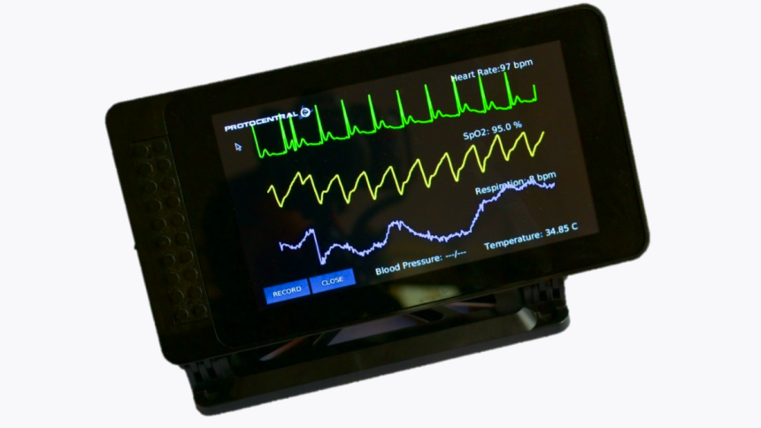
The heart’s contractions have an electrical nature that can be captured from the skin by placing electrodes and processing the signal to plot a graph. This graph is what is known as an ECG and it can be used to diagnose heart failure or monitor a patient’s stress passively. A healthy ECG has specific universal features for humans, such as P, Q, R, S, and T waves, plus the QRS complex, and this can be used as a template to check if the heart is healthy. Here’s how to build an ECG machine that can measure these parameters as a DIY project.
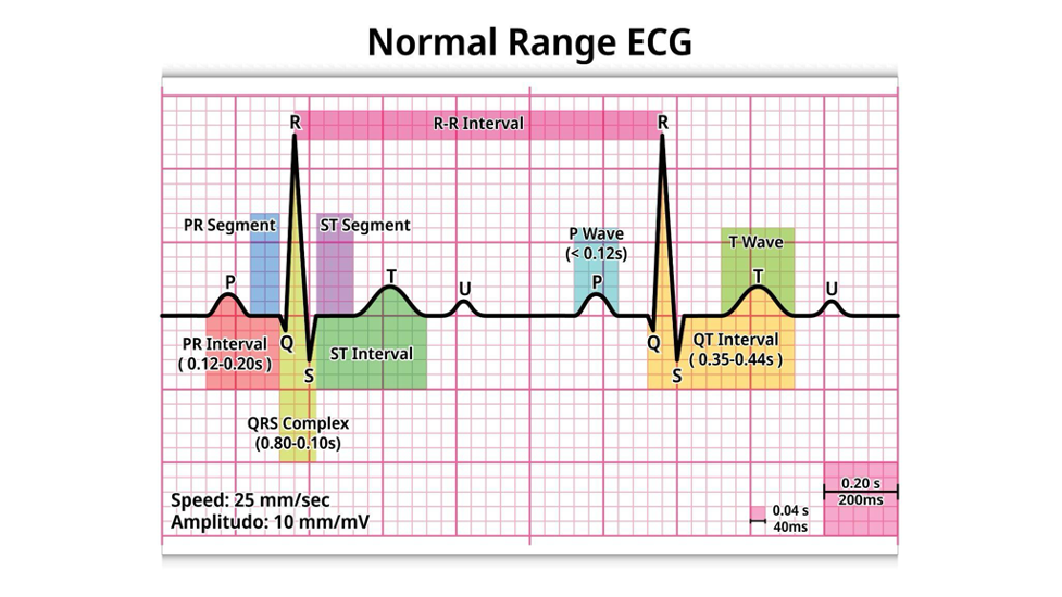
A normal range ECG
How To Build a DIY ECG Machine
To record an ECG, you have to consider the signal size, noise coming from other parts of the body, and environmental noise. Therefore, the machine’s circuit must compensate for this using the following parts.
- Differential amplifier to amplify the heart rate signal size
- Notch filter to eliminate the 60 Hz noise signal present in buildings running on AC
- Low-pass filter to remove high-frequency signal noise
What You’ll Need
- 3 large breadboards (one for each circuit)
- 5 general-purpose operational amplifiers that can handle 15V (UA741 in this case)
- Two 165Ω resistors
- Three 1kΩ resistors
- Two 15kΩ, 33kΩ, 60kΩ resistors
- One 42kΩ resistor
- Two 22nF and 1μF capacitors
- One 2Μf capacitor
- Multiple jumper wires or wire harnesses
- +/-15V DC voltage source
- At least 3 electrodes
How To Build the Differential Amplifier
Since the recorded heart contraction signal is weak, this circuit amplifies it to a level that can be displayed on the oscilloscope screen. In this example, the differential amplifier will take inputs from two electrodes, check the voltage difference between them, eliminate the common noise, and amplify the signal.
It is important to note that the ECG signal amplitude will vary depending on the placement of the electrodes. The amplitude will be higher with the electrodes placed on the chest, but this setup will have a lot of noise from lung movements. So the place to take the recordings is from the wrists, which will have a tiny voltage difference (millivolts).
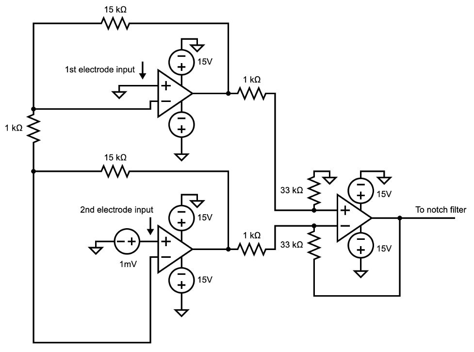
This circuit will amplify the signal 1000x. For reference, here’s the pinout diagram of the 741 op amp, which should help you with the connections.
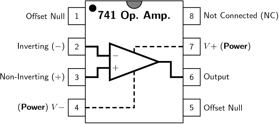
Please note that the inverting and non-inverting input are upside down in the pinout compared to the one in the circuit diagram. You won’t need pins 1, 5, and 8, and pins 4 and 7 will be hooked up to the 15V power supply (negative and positive, respectively).
Test this circuit by connecting one of the inputs (1st electrode) to the ground and the other (2nd) to a low-voltage DC source to measure its amplification properties. The gain should be somewhere between 500x and 1000x.
How To Build the Notch Filter
After amplifying the heart contraction signal, the next step is to filter the building’s AC 60 Hz noise signal. A notch filter attenuates very specific signal frequencies, which we’ll set to 60 Hz for our case.
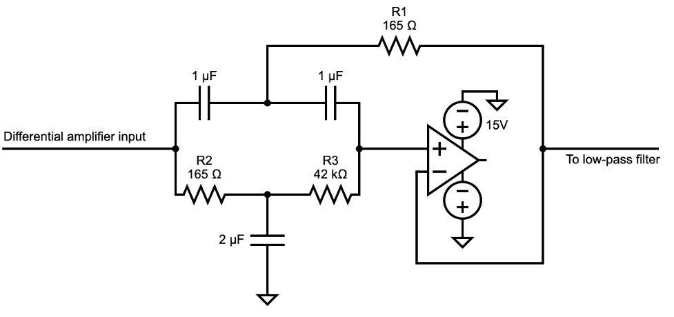
You might encounter some problems with this circuit regarding the frequency it is filtering, which should be 60 Hz. If your circuit is off this figure, tinker with the value of R1. Increasing its resistance will lower the attenuation frequency and the vice-versa is true. On paper, the values of R1 and R2 should match, but this isn’t usually the case practically. So you can use a resistor box as R1 to find the best value.
For testing, use a function generator that outputs a 60 Hz sine wave and check the output on an oscilloscope. It should be 10% (-20dB) of the input’s amplitude.
How To Build the Low-Pass Filter
The purpose of a low pass filter in the ECG machine is to remove all noise frequencies above the ECG, meaning we have to set a cutoff frequency. Anything above this figure should be eliminated by this circuit. Heartbeats occur at 1–3 Hz, but ECG frequencies can go up to 50 Hz. In this circuit, we’ll cut all frequencies above 80 Hz.
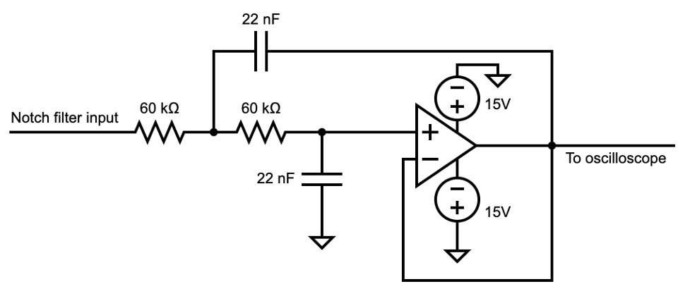
Test this circuit using a function generator. Sine waves lower than 80 Hz should pass through untouched but higher ones will be cut off.
Test The ECG Machine
Connect these three circuits and hook up the electrodes to your wrists. The third electrode is for grounding and should be placed on your leg. The grounding in the circuit is only for simulation purposes, so eliminate these components plus the low-voltage power supply. Once in place, connect the low-pass filter to an oscilloscope and observe your ECG.
Final Thoughts
This project is a simplified version of an ECG machine, so you can dig further on the internet to improve the circuit. While enhancing the prototype, I recommend using custom medical wiring harnesses for this project to ensure reliable signal transmission, precise fitting, and maximum durability. Cloom Tech specializes in manufacturing and assembling these custom medical cable assemblies, so check out their services to find out more or get a free quote.
Lynn Martelli is an editor at Readability. She received her MFA in Creative Writing from Antioch University and has worked as an editor for over 10 years. Lynn has edited a wide variety of books, including fiction, non-fiction, memoirs, and more. In her free time, Lynn enjoys reading, writing, and spending time with her family and friends.